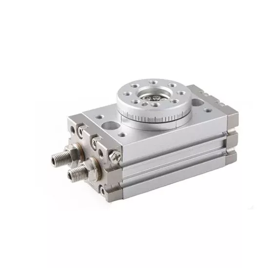
Pneumatic rotary actuators with rack-and-pinion structure and a higher-precision working platform are for sale. This series of rotary actuators comes with a number of optional sizes along with two modes of buffer. With these characteristics, this type of pneumatic rotary actuator will surely make a greatly useful part in your pneumatic system.
Product features
- Higher manufacturing precision of working platform: The manufacturing precision of working platform is high, facilitating installation and is of precise orientation. The working platform has a through hole in the center, and pipes can be located and passed through the hole.
- Double cylinder structure brings about double output.
- Two modes of buffer are offered for selection, including adjustment bolt buffer and internal shock absorber with the latter even better.
- Rack and pinion design makes for stable functioning.
- The device comes with integral magnetic switch slots
- Three types of size are selectable which are mini-sized (2, 3 & 7), middle-sized (10, 20, 30 & 50) and large-sized (70, 100 & 200) rotary cylinders.
- Simple installation: Guide holes are designed on both sides of the cylinder body (10~200) or undersurface (2~7).
Specification
| Model | ATO-RTC-HRQ | |||||||||
| Type | 2 | 3 | 7 | 10 | 20 | 30 | 50 | 70 | 100 | 200 |
| Acting type | Double rack and pinion (Double acting) | |||||||||
| Fluid | Air (to be filtered by 40 um filter element) | |||||||||
| Operating pressure | With adjustable bolt | 0.15~0.7MPa (22~100psi) (1.5~7.0bar) | ||||||||
| With internal shock absorber | – | 0.15~0.7MPa (22~100psi) (1.5~7.0bar) | ||||||||
| Proof pressure | 1.2MPa (175psi) (12.0bar) | |||||||||
| Temperature | -20~70℃ | |||||||||
| Angle adjustment range | 0~190° | 0~190° | ||||||||
| Repeatable precision | With adjustable bolt | 0.2° | ||||||||
| With internal shock absorber | – | 0.05° | ||||||||
| Theoretic moment (Nm) (0.5MPa) | 0.2 | 0.33 | 0.63 | 1.1 | 2.2 | 2.8 | 5 | 7.5 | 11 | 22 |
| Cushion type | With adjustable bolt | Rubber bumper | ||||||||
| With internal shock absorber | – | Shock absorber | ||||||||
| Port size | End ports | M5 × 0.8 | 1/8″ [Note1] | |||||||
| Side ports | M5 × 0.8 | |||||||||
| Weight | 120g | 175g | 270g | 535g | 940g | 1260g | 2060g | 2890g | 4100g | 7650g |
| [Note1]: PT thread, G thread and NPT thread are available.HRQ series are all attached with magnet. |
Inner structure and material of major parts
| NO. | Item | Material |
| 1 | Adjustable bolt | Carbon steel |
| 2 | Hexagon nut | Carbon steel |
| 3 | Seal washer | Carbon steel & Rubber |
| 4 | Front cover | Aluminum Alloy |
| 5 | Body | Aluminum Alloy |
| 6 | Hexagon socket head set bolt | Carbon steel |
| 7 | Table | Aluminum Alloy |
| 8 | Hexagon socket head set bolt | Carbon steel |
| 9 | Guide pin/flat key | Carbon steel |
| 10 | Deep-groove bearing | Subassembly |
| 11 | Bearing retainer | Aluminum Alloy |
| 12 | Deep-groove bearing/Needle bearing | Subassembly |
| 13 | Back cover | Aluminum Alloy |
| 14 | Steel ball | Stainless steel |
| 15 | Piston seal | NBR |
| 16 | Wear ring | Ware resistent material |
| 17 | Magnet | Rare earths |
| 18 | Rack | Stainless steel/Carbon steel |
| 19 | Pinion | Chrome molybdenum steel |
| 20 | O-ring | NBR |
| 21 | Bumper | NBR |
| 22 | O-ring | NBR |
| 23 | O-ring | NBR |
| 24 | Hexagon screw | Stainless steel |
| 25 | Shock absorber | Subassembly |
Dimensions (unit: mm)
| Type/Item | A | AC | AD | B | BA | C | CA | CB | E | EA | EB | EC | G | J | JA | JB | K | KA | KC | L | LA | LB | LC | P | PA |
| 2 | 76 | 64 | 8 | 32 | 30 | 28 | 18 | 10 | M5×0.8 | 12 | 12 | 9.5 | 4 | 6 | 3.5 | 37 | M4×0.7 | 7.5 | 3.5 | M4×0.7 | 4 | 35 | 4.5 | M5×0.8 | 12.5 |
| 3 | 82 | 70 | 8 | 36.5 | 34.5 | 30.5 | 20.5 | 10 | M5×0.8 | 12 | 15.5 | 10.5 | 5 | 7.5 | 4.5 | 43 | M5×0.8 | 8.5 | 4.5 | M4×0.7 | 4 | 40 | 4.5 | M5×0.8 | 15.5 |
| 7 | 94.5 | 79.5 | 8 | 43 | 41 | 34.5 | 23 | 11.5 | M6×1.0 | 15 | 18.5 | 12 | 6 | 7.5 | 4.5 | 50 | M5×0.8 | 8.5 | 4.5 | M5×0.8 | 5 | 50 | 5 | M5×0.8 | 18.5 |
| Type/Item | PB | Q | QA | QB | R | RA | S | SA | T | TA | U | UA | V | VA | VB | VC | W | WA | WB | X | XA | XB | Y | YA | YB |
| 2 | 10 | M5×0.8 | 4 | 6 | 14 (H9) | 2.5 | 29 (h9) | 5.5 | 29.5 (h9) | 4 | 5 (H9) | 1.5 | M3×0.5 | 3.5 | 34 | 18.5 | M3×0.5 | 5.5 | 21 | 2 (H9) | 2 | 10.5 | 2 (H9) | 2 | 24 |
| 3 | 12 | M5×0.8 | 4 | 7.5 | 17 (H9) | 2.5 | 33 (h9) | 5.5 | 34 (h9) | 4 | 6 (H9) | 1.5 | M3×0.5 | 3.5 | 38 | 23 | M3×0.5 | 5.5 | 25 | 2 (H9) | 2 | 12.5 | 2 (H9) | 2 | 28 |
| 7 | 14 | M5×0.8 | 4 | 9 | 20 (H9) | 3 | 39 (h9) | 6.5 | 40 (h9) | 4.5 | 7 (H9) | 1.5 | M4×0.7 | 4.5 | 45 | 30 | M4×0.7 | 6.5 | 29 | 3 (H9) | 3 | 14.5 | 3 (H9) | 3 | 32 |
| Type/Item | A (With internal shock absorber) | A (With adjustment bolt) | AC | AD | B | BA | C | CA | CB | E | EA (With internal shock absorber) | EA (With adjustment bolt) |
| 10 | 123 | 112 | 92 | 9.5 | 50 | 54 | 47 | 34 | 13 | M10×1.0 | 31 | 20 |
| 20 | 169 | 145.3 | 117 | 11 | 65 | 69 | 54 | 37 | 17 | M12×1.0 | 52 | 28.3 |
| 30 | 178.5 | 154.5 | 127 | 11.5 | 70 | 74 | 57 | 40 | 17 | M12×1.0 | 51.5 | 27.5 |
| 50 | 212 | 185.9 | 152 | 15 | 80 | 84 | 66 | 46 | 20 | M14×1.5 | 60 | 33.9 |
| Type/Item | EB | EC | G | J | JA | JB | JC | K | KA | KC | P | PA | PB | Q | QA | QB | R | RA | S | SA |
| 10 | 20.5 | 14 | 5 | 11 | 6.5 | 60 | 27 | M8×1.25 | 12 | 6.5 | M5×0.8 | 34.5 | 28 | M5×0.8 | 4.5 | 29 | 20(H9 | 4.5 | 45 (h9) | 8 |
| 20 | 27.5 | 16 | 9 | 14 | 8.5 | 76 | 34 | M10×1.5 | 15 | 8.5 | M5×0.8 | 47 | 30 | M5×0.8 | 6 | 30 | 28(H9 | 6.5 | 60 (h9) | 10 |
| 30 | 29 | 18.5 | 9 | 14 | 8.5 | 84 | 37 | M10×1.5 | 15 | 8.5 | 1/8″ | 50 | 32 | M5×0.8 | 6.5 | 34 | 32(H9 | 5 | 65 (h9) | 10 |
| 50 | 38 | 22 | 10 | 18 | 10.5 | 100 | 50 | M12×1.75 | 18 | 10.5 | 1/8″ | 63 | 38 | M5×0.8 | 10 | 38 | 35 (H9) | 5.5 | 75 (h9) | 12 |
| Type/Item | T | TA | U | UA | V | VA | W | WA | WB | X | XA | XB | Y | YA | YB | YC |
| 10 | 46 (h9) | 4.5 | 15 (H9) | 3 | M5×0.8 | 8 | M5×0.8 | 8 | 32 | 3 (H9) | 3.5 | 16 | 3 (H9) | 3.5 | 56 | 40 |
| 20 | 61 (h9) | 6.5 | 17 (H9) | 2.5 | M6×1.0 | 8 | M6×1.0 | 10 | 43 | 4 (H9) | 4.5 | 21.5 | 4 (H9) | 4.5 | 74 | 50 |
| 30 | 67 (h9) | 6.5 | 22 (H9) | 3 | M6×1.0 | 8 | M6×1.0 | 10 | 48 | 4 (H9) | 5 | 24 | 4 (H9) | 4.5 | 80 | 58 |
| 50 | 77 (h9) | 7.5 | 26 (H9) | 3 | M8×1.25 | 8 | M8×1.25 | 12 | 55 | 5 (H9) | 6 | 27.5 | 5 (H9) | 5.5 | 92 | 68 |
| Type/Item | A (With internal shock absorber) | A (With adjustment bolt) | AC | AD | B | BA | BC | C | CA | CB | CD | E | EA (With adjustment bolt) |
| 70 | 206.8 | 244 | 92 | 17 | 92 | 88 | 84 | 75 | 53 | 22 | 36 | M20×1.5 | 36.8 |
| 100 | 225.7 | 263 | 117 | 17 | 102 | 99 | 95 | 86 | 59 | 27 | 42 | M20×1.5 | 36.7 |
| 200 | 279.5 | 316.5 | 127 | 24 | 120 | 117 | 113 | 106 | 74 | 32 | 57 | M27×1.5 | 39.5 |
| Type/Item | EA (With internal shock absorber) | EB | G | J | JA | JB | JC | K | KA | KC | P | PA | PB | Q | QA | R | RA | S | SA |
| 70 | 74 | 42 | 16 | 17.5 | 12 | 110 | 57 | M12×1.75 | 18 | 10.5 | 1/8″ | 75 | 44 | M5×0.8 | 25 | 46 (H9) | 5 | 88 (h9) | 12.5 |
| 100 | 74 | 50 | 19 | 17.5 | 12 | 130 | 66 | M12×1.75 | 18 | 10.5 | 1/8″ | 85 | 50 | M5×0.8 | 29 | 56 (H9) | 6 | 98 (h9) | 14.5 |
| 200 | 76.5 | 60 | 24 | 20 | 12.5 | 150 | 80 | M16×2.0 | 25 | 14 | 1/8″ | 103 | 62.5 | M5×0.8 | 36 | 64 (H9) | 9 | 116 (h9) | 16.5 |
| Type/Item | T | TA | U | UA | V | VA | W | WA | WB | X | XA | XB | Y | YA | YB | YC | Z | ZA |
| 70 | 90 (h9) | 9 | 22 (H9) | 3.5 | M8×1.25 | 10 | M8×1.25 | 12.5 | 67 | 5 (H9) | 5.5 | 33.5 | 5 (H9) | 3.5 | 110 | 80 | 5 (H9) | 3.5 |
| 100 | 100 (h9) | 12 | 24 (H9) | 3.5 | M8×1.25 | 10 | M8×1.25 | 14.5 | 77 | 6 (H9) | 6.5 | 38.5 | 6 (H9) | 4.5 | 120 | 100 | 6 (H9) | 4.5 |
| 200 | 118 (h9) | 15 | 32 (H9) | 5.5 | M12×1.75 | 13 | M12×1.75 | 16.5 | 90 | 8 (H9) | 1/8″ | 45 | 8 (H9) | 4.5 | 140 | 110 | 8 (H9) | 6.5 |
Tips: How to select a pneumatic rotary actuator
- Determine the following working conditions of a pneumatic rotary actuator according to the actual situation:1.1 Rotation angle θ: The actual rotation angle must be within the maximum allowed range of rotation angle of cylinder.1.2 Rotation time t: The rotation time must be within the maximum allowed range of rotation time of cylinder.1.3 Installation position of cylinder: Allow enough installation space, so as to ensure leaving adequate space for rotation of cylinder and workpieces.1.4 Determination of loading mass and loading shape.
- Calculation of necessary torque needed when loading rotation (T(N.m))Calculate the necessary moment required for loading rotation according to the formula below, and combine with the torque diagram of actual effect, to choose the pneumatic rotary actuator with suitable torque output.2.1 Calculation method of moment of inertia in different conditions
Diagram Description Calculation formulaof moment of inertia Rotation radius Diagram Description Calculation formulaof moment of inertia Rotation radius d: Diameter (m) m: Mass (kg) a: Sheet length (m) b: Length of side (m) m: Mass (kg) Note: no special installation direction Note: no special installation direction d1: Diameter (m) d2:Diameter (m) m1: d1 Mass (kg) m2: d2 Mass (kg) a: Sheet length (m) m: Mass (kg) Note: Compared with d2, disregard d1 if d1 is extremely tiny Note: no special installation direction d: Diameter (m) m: Mass (kg) a: Sheet length (m) m: Mass (kg) Note: no special installation direction Note: 1. horizontal installation. 2. pay attention to the change of movement time in case of vertical installation. r: Radius (m) m: Mass (kg) a: Sheet length (m) b: Distance between the rotation axis and the gravity center of loading (m) m: Mass (kg) Note: no special installation direction Note: the cuboids are the same. a1: Sheet length (m) a2: Sheet length (m) m1: a1 Mass (kg) m2: a2 Mass (kg) a: Tooth number of gear b: Tooth number of loading gear Note: 1. horizontal installation. 2. pay attention to the change of movement time in case of vertical installation. a1: Vertical distance between the rotation axis and the concentrated loading (m) a2: Length of arm (m) m1: Mass of concentrated loading (kg) m2: Mass of arm (kg) a1: Sheet length (m) a2: Sheet length (m) b: Length of side (m) m1: a1 Mass (kg) m2: a2 Mass (kg) Note: 1. horizontal installation. 2. compared with m, disregard if m is extremely tiny. 3. calculate K according to the shape of concentrated loading row by row. For example, when the loading is spheroid, K=2r²/5 Note: 1. horizontal installation. 2. pay attention to the change of movement time in case of vertical installation. - Calculation of maximum movement energy E(max, J):Calculate the maximum movement energy according to the formula below, and make sure that the maximum movement energy is within allowed energy range of the chosen pneumatic cylinder as excessively large movement energy would lead to damage of inner parts, please choose rotation cylinder attached with shock absorber when the movement energy is fairly large.
- Calculation of loading rateCalculate the loading rate according to the formula below, and the loading rate must not be more than 1.
- Determination methodIt could be used only when the chosen pneumatic rotary actuator must meet the requirements of article 2, 3 and 4 simultaneously.