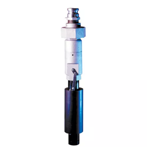
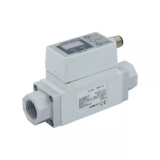
Lightweight air flow switch with digital display can monitor data in real time. It is designed with water sensor to transmit data to the mainboard.
Specification
| Model | ATO-NPF2A751-04 | |
| Port Size Rc (PT) | 1/2 inch | |
| Measured Fluid | Air, Nitrogen (N2) | |
| Rated Flow Range | 50~500L/min | |
| Minimum Set Unit | 5L/min | |
| Accumulated Pulse Flow Rate Exchange Value(Pulse Width: 50 ms) | 5L/pulse | |
| Display Units | Instantaneous Flow Rate | L/min, CFMx10-1 |
| Accumulated flow | L, ft3 x10-1 | |
| Operating Pressure Range | -50KPa~0.75MPa | |
| Operating Fluid Temperature | 0~50℃ | |
| Power Supply Voltage | DC12~24V±10% | |
| Current Consumption | 170mA or less | |
| Accumulated Flow Range | 0~999999L | |
| Detection Type | Heater type | |
| Accuracy | ±5% F.S. | |
| Repeatability | ±2% F.S. | |
| Temperature Characteristics | ±3% F.S. (15 to 35°C, 25°C reference), ±5% F.S. (0 to 50°C, 25°C reference) | |
| Output | Switch Output | NPN open collector maximum load current: 80 mAInternal voltage drop: 1 V or less.Maximum applied voltage: 30 V, 2 outputs |
| Accumulated Pulse Output | NPN or PNP open collector (same as switch output) | |
| Hysteresis | Hysteresis mode: Variable (can be set from 0)Window comparator mode: 3-digit fixed | |
| Response Time | Lights up when output is turned ONOUT1: GreenOUT2: Red | |
| Status LED’s | 1 sec. or less | |
| Environment | Enclosure | IP65 |
| Operating Temperature Range | Operating: 0 to 50°CStored: –25 to 85°C (with no freezing and condensation) | |
| Withstand Voltage | 1000 VAC for 1 minute between terminals and housing | |
| Insulation Resistance | 50 mΩ or more (500 VDC measured via megohmmeter) between terminals and housing | |
| Noise Resistance | 1000V P-P Pulse width 1μs, duration 1 ns | |
| Wire Size | M12 connector (3m) | |
| Weight | 1kg |
Flow Rate Diagram
Voltage Output: A: 1V, B: 5VCurrent Output: A: 4mA, B: 20mA
Pin Number & Wire Color
| Pin Number | Content | Wire Color |
| 1 | DC (+) | Brown |
| 2 | OUT2 | White |
| 3 | DC (-) | Blue |
| 4 | OUT1 | Black |
Dimensions (Unit: mm)
Details
Tips for installing an air flow switch
- The flow switch needs to be installed on the straight section of the pipe or air duct
- It is necessary to ensure that there are long enough straight pipes before and after the installation position of the flow switch. The length of the normal straight pipe should be greater than 10 times the diameter of the pipe.
- Avoid installing or wiring flow switches near elbows, other fittings, valves, drains, narrow or wide pipe sections, and any other features that may cause significant fluctuations in flow through the area.